| N TYPE CONNECTOR |
 Description
|
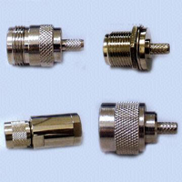
Cableslink N connectors are medium-sized, threaded
coupling connectors designed for use from DC to 11 GHz. N series connector
is impedance matched to 50 ohms cables. N connector variety of clamp,
crimp, and solder types. |
 Coaxial Connector - N Type
Screw-on Standard, RF Coaxial Connectors (N-Type), OEM/ODM
 |
Key Specifications/Special
Features:
-
Medium-sized, threaded coupling connectors designed
for use from DC to 11GHz
-
N series connector impedance matches to 50 ohms cables
-
N connector variety: clamp, crimp, and solder types
-
Connector body
Material: brass
Finish: nickel or gold plating
-
Center contact
Material: Male: brass
Female: beryllium copper, phosphor bronge
Finish: gold plating
-
Insulation
Material: teflon
Finish: none
Gasket
Material: silicone rubber
Finish: none
-
Crimp ferrule
Material: annealed copper
Finish: same as body
-
Electrical
Impedance: 50 ohms
Frequency range: 11GHz
VSWR: 1.15 + 0.015f x GHz max
Working voltage: 500 volts rms
Contact resistance:
center contact 1.5 milliohms max
outer contact 1.5 milliohms max
Insulation resistance: 5000 megohms min
Dielectric withstanding voltage: 2500 volts rms
-
Mechanical and environmental
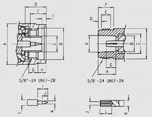
Mating: 5/8-inch - 24UNEF thread coupling
Durability: 500 matings
Cable retention: 40 lbs min
Coupling nut retention: 100 lbs min
Temperature range: -65 to +165 degrees Celsius
Vibration: MIL-STD-202 method 204 test condition D
Thermal shock: MIL-STD-202 method 213 test condition I
Corrosion: MIL-STD-202 method 101 test condition B
|
| PLUG |
| Letter |
MINIMUM |
MAXIMUM |
| A |
|
 21.01 m/m
 |
| B |
16.0 m/m |
|
| C |
|
8.38 m/m |
| D |
10.11 m/m |
10.46 m/m |
| E |
5.33 m/m |
5.84 m/m |
| F |
0.41 m/m |
1.52 m/m |
| G |
4.50 m/m |
5.00 m/m |
| H |
4.01 m/m |
4.27 m/m |
| I |
5.22 m/m |
5.84 m/m |
| J |
3.22 m/m |
4.32 m/m |
| K |
1.60 m/m |
1.68 m/m |
| L |
3.00 m/m |
3.15 m/m |
|
| JACK |
| Letter |
MINIMUM |
MAXIMUM |
| A |
8.53 m/m |
8.74 m/m |
| B |
8.03 m/m |
8.13 m/m |
| C |
6.96 m/m |
7.06 m/m |
| D |
1.19 m/m |
1.96 m/m |
| E |
4.37 m/m |
5.13 m/m |
| F |
10.72 m/m |
|
| G |
4.75 m/m |
5.26 m/m |
| H |
9.04 m/m |
9.19 m/m |
I |
|
15.93 m/m |
J |
1.72 m/m |
1.78 m/m |
K |
3.00 m/m |
3.15 m/m |
L |
5.33 m/m |
|
|
| Material |
| |
Material |
Finish |
| Connector body |
Brass |
Nickel or gold plating |
| Center contact |
Male-Brass |
Gold plating |
| Female-(1)Beryllium copper
(2)Phosphor bronge |
Gold plating |
| Insulation |
Teflon |
None |
| Gasket |
Silicone Rubber |
None |
| Crimp ferrule |
Annealed copper |
Same as body |
|
| Electrical |
| Impedance |
50 ohms |
| Frequency
Range |
11GHz |
| VSWR |
1.15+0.015fxGHz max |
| Working
Voltage |
500 volts rms |
| Contact
Resistance |
center contact 1.5Milliohms max
outer contact 1.5 Milliohms max |
| Insulation Resistance |
5000 Megohms min |
| Dielectric withstanding Voltage |
2500 Volts rms |
|
| Mechanical & Environmental |
| Mating |
5/8"-24UNEF Thread coupling |
| Durability |
500 matings |
| Cable Retention |
40 lbs min |
| Coupling
Nut Retention |
100 lbs min |
| Temperature Range |
'-65'C TO +165'C |
| Vibration |
MIL-STD-202 Method 204 Test Cond D |
| Thermal Shock |
MIL-STD-202 Method 213 Test Cond I |
| Corrosion |
MIL-STD-202 Method 101 Test Cond B |
|
Copyright© 2004 cableslink.com, all rights reserved.