| SMA CONNECTOR |
 Description
|
ケーブルリングSMAコネクタは精確コネクタとしてRFの設計応用に対応する、周波数18GHzに達します。
Cableslink SMA connectors are precision connectors for microwave application
up to 18 GHz. SMA connectors are also used to provide interconnections
from printed circuit board striplines to coaxial cable.
|
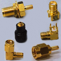
Coaxial Connector - SMA
RF Coaxial Connectors (SMA Type) for Flexible and Semi-Rigid Cables
for Microwave RF Application
|
Key Specifications/Special Features:
- Precision connectors for microwave appication up to 18 GHz
- Used to provide interconnections from printed circuit board striplines
to coaxial cable
- Connector body
Material: brass/stainless steel
Finish: nickel or gold plating/gold or passivated
- Center contact
Material: (male) brass, (female) beryllium copper
Finish: gold plating/gold plating
- Insulation
Material: teflon
Finish: none
- Gasket
Silicone rubber
Finish: none
- Crimp ferrule
annealed copper
Finish: same as body
- Electrical
Impedance: 50 ohms
Frequency range: for flexible cable (12.4GHz), for semi-rigid cable
(18.0 GHz)
VSWR:
1.10 + 0.01f GHz straight connector
1.20 + 0.015f GHz right angle connector
Working voltage: 250 volts rms
Contact resistance:
Center contact 3.0 milliohms max
Outer contact 2.0 milliohms max
Insulation resistance: 5000 megohms min
Dielectric withstanding voltage: 500 volts rms
- Mechanical and environmental
Mating: 1/4-inch -36 thread coupling
Durability: 500 matings
Cable retention: 20 lbs min.
Coupling nut retention: 40 lbs min
Temperature range: -65 to + 165 degrees Celsius
Vibration: MIL-STD-202 method 204 test condition D
Thermal shock: MIL-STD-202 method 213 test condition I
Corrosion: MIL-STD-202 method 101 test condition B
|
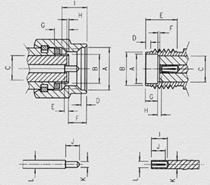
| PLUG |
| Letter |
MINIMUM |
MAXIMUM |
| A |

6.48 m/m |
6.73 m/m |
| B |
4.34 m/m |
4.59 m/m |
| C |
4.10 m/m |
4.13 m/m |
| D |
0.64 m/m |
1.14 m/m |
| E |
0.00 m/m |
0.13 m/m |
| F |
2.59 m/m |
3.35 m/m |
| G |
2.03 m/m |
|
| H |
0.00 m/m |
0.25 m/m |
| I |
3.71 m/m |
4.32 m/m |
| J |
2.03 m/m |
2.29 m/m |
| K |
0.90 m/m |
0.93 m/m |
| L |
1.25 m/m |
1.29 m/m |
|
| JACK |
| Letter |
MINIMUM |
MAXIMUM |
| A |
4.60 m/m |
4.67 m/m |
| B |
5.28 m/m |
5.49 m/m |
| C |
4.10 m/m |
4.13 m/m |
| D |
0.38 m/m |
1.14 m/m |
| E |
3.81 m/m |
|
| F |
0.00 m/m |
0.25 m/m |
| G |
1.88 m/m |
1.98 m/m |
| H |
0.00 m/m |
0.25 m/m |
| I |
2.54 m/m |
|
| J |
1.91 m/m |
2.41 m/m |
| K |
1.25 m/m |
1.29 m/m |
| L |
0.94 m/m |
0.99 m/m |
|
| Material |
| |
Material |
Finish |
| Connector body |
Brass |
Nickel or gold plating |
| Stainless steel |
Gold or passivated |
| Center contact |
Male-Brass |
Gold plating |
| Female-Beryllium copper |
Gold plating |
| Insulation |
Teflon |
None |
| Gasket |
Silicone Rubber |
None |
| Crimp ferrule |
Annealed copper |
Same as body |
|
| Electrical |
| Impedance |
50 ohms |
| Frequency Range |
For flexible cable(12.4GHz),for
semi-rigid cable(18.0 GHz) |
| VSWR |
1.10+0.01f GHz straight connector
1.20+0.015f GHz right angle connector |
| Working Voltage |
250 volts rms |
| Contact Resistance
|
center contact 3.0Milliohms max
outer contact 2.0 Milliohms max |
| Insulation Resistance |
5000 Megohms min |
| Dielectric withstanding
Voltage |
500 Volts rms |
|
| Mechanical & Environmental |
| Mating |
1/4"-36 thread coupling |
| Durability |
500 matings |
| Cable Retention |
20 lbs min |
| Coupling Nut Retention |
40 lbs min |
| Temperature Range |
'-65'C TO +165'C |
| Vibration |
MIL-STD-202 Method 204 Test Cond
D |
| Thermal Shock |
MIL-STD-202 Method 213 Test Cond
I |
| Corrosion |
MIL-STD-202 Method 101 Test Cond
B |
|
Copyright© 2004 cableslink.com, all rights reserved.